
Bearing Type Selection: A Decision Matrix with a Worked Example
Bearing Type Selection: A Decision Matrix with a Worked Example
Most “how to choose a bearing” pages hand you a comparison table and stop there. A table tells you
what a deep groove ball bearing is; it does not tell you whether that bearing survives
20,000 hours at 720 rpm under 8 kN of radial load, 2.5 kN of axial load, and 0.4° of shaft
misalignment. That second question is the one that actually costs money when it is answered wrong.
This guide does both. First, a decision matrix that narrows ten-plus bearing
families down to a shortlist using five measurable inputs. Then a fully worked selection
example: we compute the equivalent dynamic load P, the ISO 281 basic rating life
L10h, and the required dynamic load rating C, and compare three
candidate arrangements numerically. You get the arithmetic, not another checklist.
About the numbers: all load ratings, factors and tolerance angles
in the worked example are illustrative magnitudes for teaching the method, not catalogue
values for any specific manufacturer’s product. Always substitute the ratings from the catalogue of
the bearing you intend to buy.
1. Why a comparison table is not a selection method
A table is a lookup device: you already know the answer, and you want to confirm its properties.
Selection runs in the opposite direction — you have a load case and need to arrive at the answer.
Three failure modes show up repeatedly when people skip the arithmetic:
- Capacity is not a single number. “Roller bearings are stronger” is true for
radial load and misleading for speed, friction, and misalignment. A spherical roller bearing
that thrives in a crusher is a poor choice for a high-speed spindle. - Life is dominated by one exponent. Because L10 scales with
(C/P)p, and p is 3 for ball bearings but 10/3 for roller bearings,
a modest change in equivalent load or rated capacity moves life by multiples — not percentages.
Guessing here is expensive. - The binding constraint is often not load. Misalignment, speed, envelope,
minimum load, and lubrication frequently eliminate a bearing that passes the life calculation
comfortably. In our worked example below, the arrangement with the longest calculated
life is rejected for exactly this reason.
The fix is a sequence: define inputs → eliminate by hard constraints → compute
P and life for the survivors → check the secondary constraints → only then pick a
part number.

2. The five inputs that decide the type
Before looking at any catalogue, fix these five. Everything downstream is a consequence of them.
| Input | What to establish | Why it decides the type |
|---|---|---|
| Load direction & ratio | Radial Fr, axial Fa, combined, shock content, and the ratio Fa/Fr | Separates pure-radial types (cylindrical, needle) from combined-load types (deep groove, angular contact, tapered, spherical) and pure-axial types (thrust) |
| Speed | Continuous and peak rpm; n·dm where dm is the mean diameter | Ball bearings tolerate higher speed and run cooler; roller types generate more heat and have lower limiting speeds |
| Misalignment | Expected angular error between shaft and housing, in degrees | Rigid types (tapered, cylindrical, angular contact) tolerate only a few arcminutes; self-aligning types tolerate ~1–2° |
| Envelope | Bore (set by the shaft), max outside diameter, max width | When radial space is tight, needle rollers or thin-section bearings win; when one bearing must do everything, a compact combined-load type wins |
| Life, temperature & environment | Target L10h, operating temperature, dust/water, grease vs oil, sealing | Drives required C, clearance class (C3/C4), seal type, and lubricant choice |
Note that target life sits in this list, not in the calculation section. Life is a design
input you choose; the calculation then tells you what rated capacity is needed to deliver it.
3. The bearing type decision matrix
Use this as the first-pass filter. Load direction gets you to a block; speed and misalignment cut
it down; envelope and cost pick the winner. Ratings are qualitative and typical — the worked
example in sections 5–8 shows how to replace “high” and “moderate” with numbers.
| Bearing type | Radial | Axial | Speed | Misalignment | Stiffness | Relative cost | Typical fit |
|---|---|---|---|---|---|---|---|
| Deep groove ball | Moderate | Moderate, both directions | Very high | Low (~0.15°) | Moderate | $ | Electric motors, pumps, gearboxes |
| Angular contact ball (paired) | Moderate | High, one direction per bearing | Very high | Very low | High with preload | $$ | Spindles, pumps, precision shafts |
| Self-aligning ball | Light–moderate | Light | High | High (~2°) | Low | $ | Long shafts, agricultural, conveyors |
| Four-point contact ball | Moderate | High, both directions | Medium | Low | Moderate | $$ | Compact combined load, turntables |
| Cylindrical roller (NU/N/NJ) | Very high | None (or limited, by design) | High | Very low | High | $$ | Gearboxes, motors, rolling mills |
| Tapered roller (paired) | High | High, one direction per bearing | Medium | Very low (~0.05°) | Very high | $$ | Wheel hubs, gearboxes, rolling mills |
| Spherical roller | Very high | Moderate, both directions | Low–medium | High (~1.5°) | High | $$$ | Crushers, fans, paper machines, mining |
| Needle roller | High per section height | None | Medium | Very low | Moderate | $ | Transmissions, compact radial space |
| Thrust ball / thrust roller | None | Very high | Low | Low | High axially | $$ | Vertical shafts, hooks, screw presses |
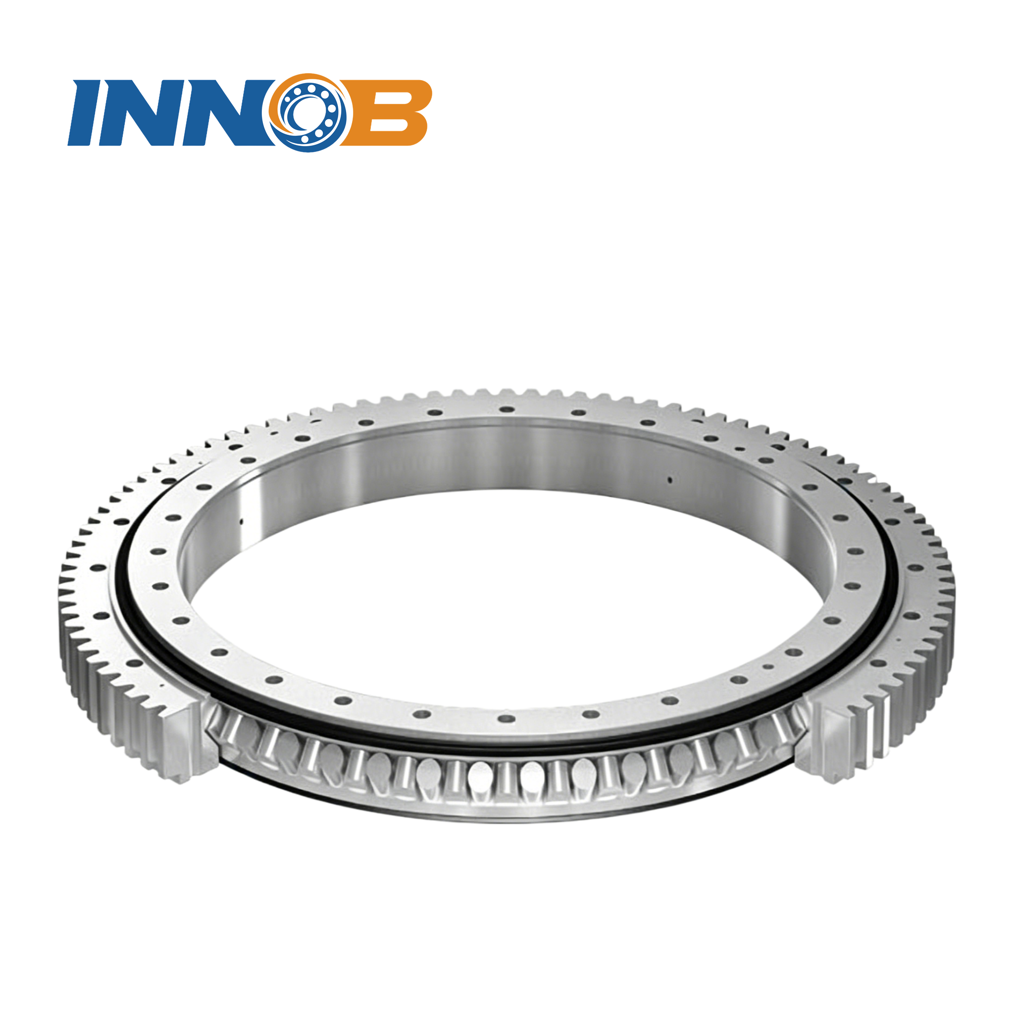
| Slewing / crossed roller | High | High + tilting moment | Low | Low–moderate | Very high | $$$$ | Cranes, excavators, robotics, radar |
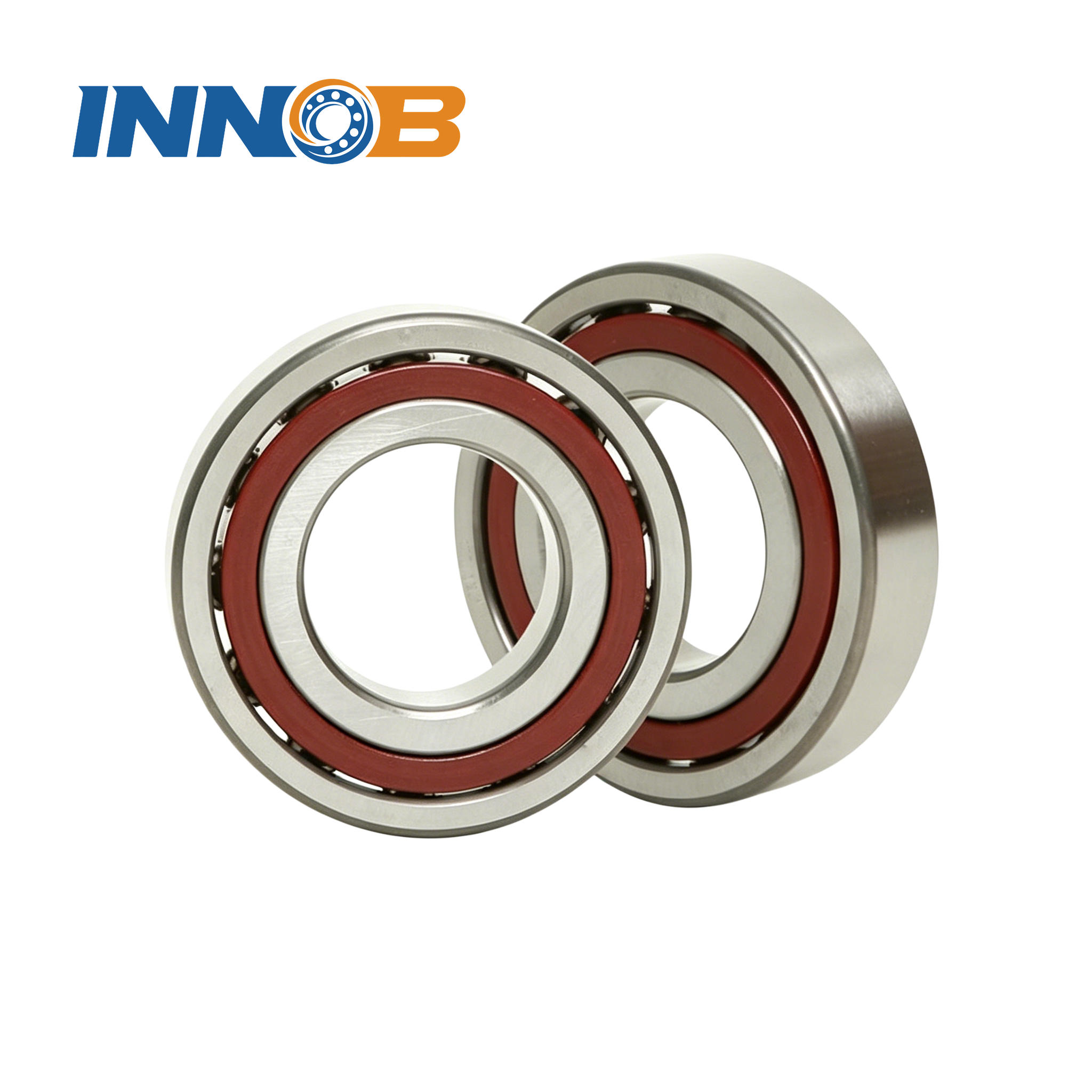
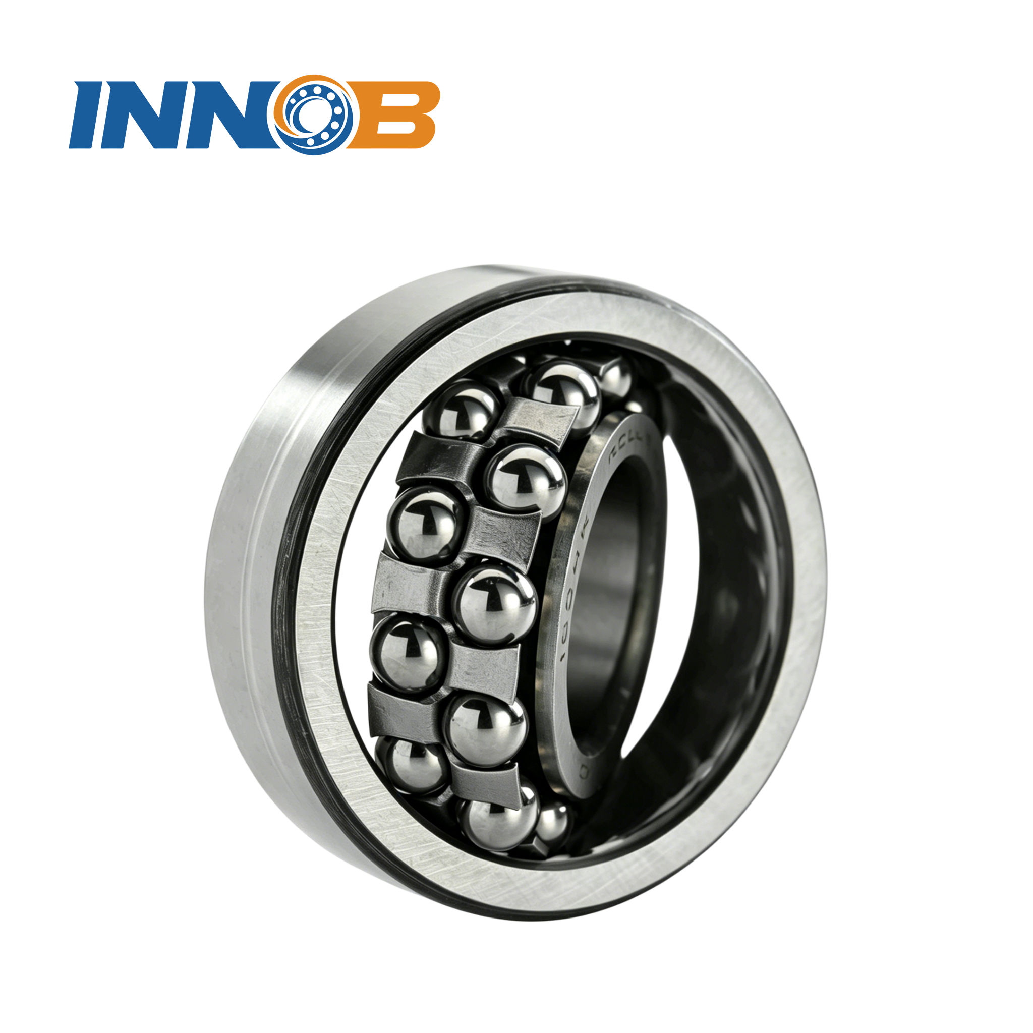
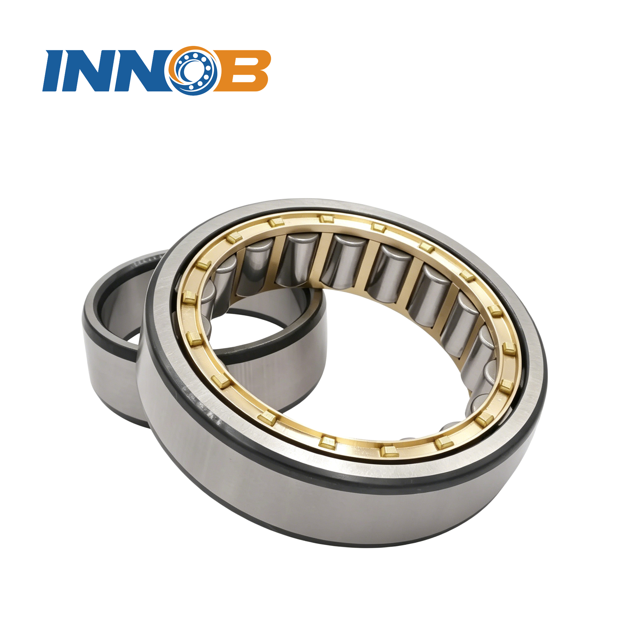
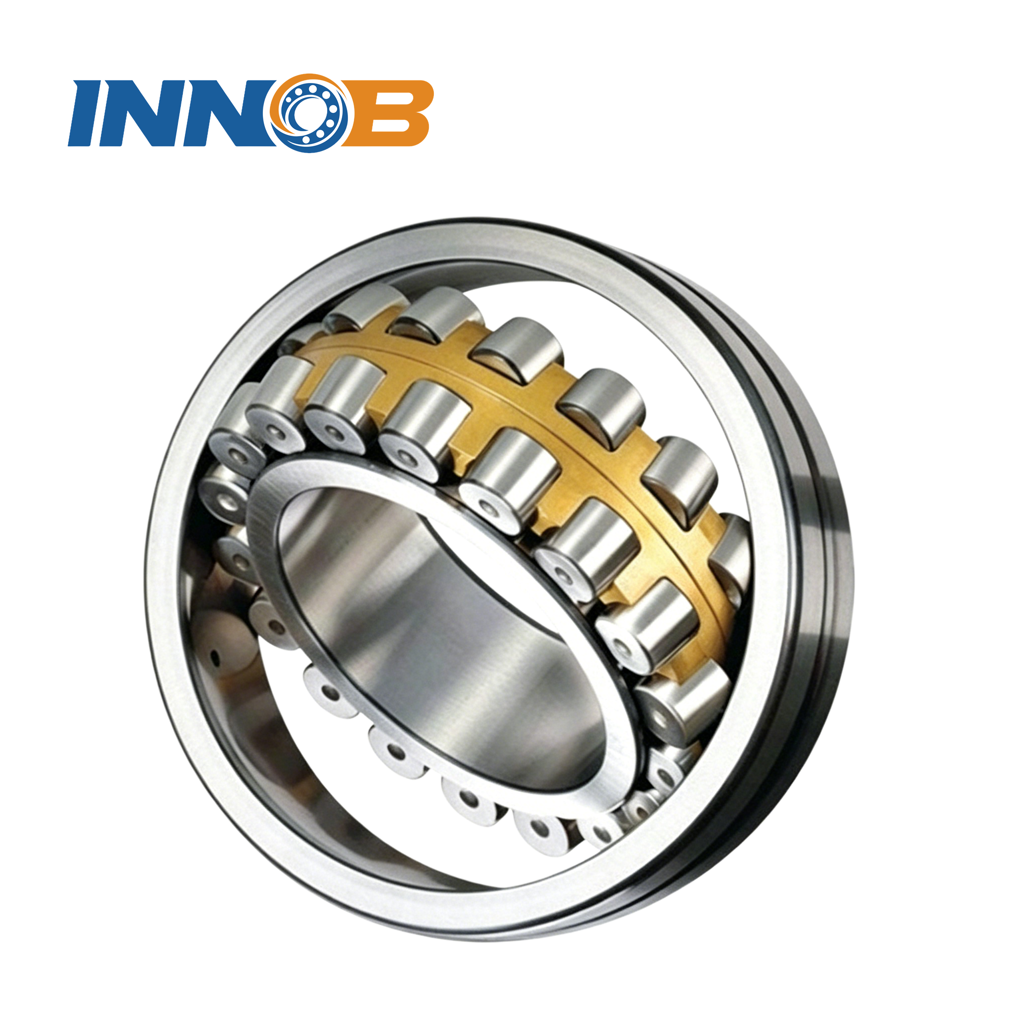
Two families sit in the “ball” block, two in “rigid roller”, one in “self-aligning”, and one at
the top for moment loads. Their mechanics are worth a picture each.
4. Worked example — the load case
A geared drive shaft on a welded frame. The shaft diameter is fixed at 70 mm by the gear bore, the
housing allows a maximum outside diameter of 150 mm and a width of 40 mm, and the frame is known to
deflect. The specified duty is:
| Parameter | Symbol | Value |
|---|---|---|
| Radial load | Fr | 8.0 kN |
| Axial load (one direction, from a helical gear) | Fa | 2.5 kN |
| Rotational speed | n | 720 rpm |
| Application / load factor (moderate shock) | fd | 1.3 |
| Target basic rating life | L10h | 20,000 h |
| Expected misalignment | — | 0.4° (welded frame, long shaft) |
| Operating temperature | — | 75 °C, grease lubricated |
| Envelope | — | bore 70 mm, OD ≤ 150 mm, width ≤ 40 mm |
Load ratio: Fa/Fr = 2.5 / 8.0 = 0.313. Combined loading, radial dominated,
with a non-trivial axial component. We now walk the sequence.
5. Step 1 — eliminate by load direction and envelope
Fa/Fr = 0.313 means the bearing must carry both components. That immediately rules out:
- Cylindrical roller (NU/N) and needle roller — high radial capacity, but no
axial capacity in the standard design. They would need a separate thrust bearing, adding width,
parts, and a lubrication split. With a 40 mm width budget and a single housing, that is
unattractive here. - Pure thrust ball / thrust roller — they cannot take the 8 kN radial load at
all, and they also need a minimum axial load to avoid skidding. - Slewing and crossed roller rings — technically capable of combined load plus
tilting moment, but sized and priced for low-speed rotational structures, not a 720 rpm shaft.
See our rolling bearing vs slewing bearing comparison for
where that boundary sits, and our slewing bearing selection overview
if the application is a rotating structure rather than a shaft.
Survivors: deep groove ball, angular contact ball (paired), tapered roller (paired),
spherical roller, four-point contact ball. Five candidates, all available in a 70 mm bore.
6. Step 2 — eliminate by misalignment before you calculate life
This is the step most selection guides skip, and the one that decides this example. The welded
frame gives 0.4° of angular error. Typical tolerable misalignment (illustrative order-of-magnitude
values, confirm against the catalogue):
| Candidate | Tolerable misalignment (typical) | 0.4° case |
|---|---|---|
| Tapered roller pair | ~0.05° | Fail — edge loading, rapid fatigue |
| Angular contact pair | ~0.03° | Fail — preload-sensitive |
| Four-point contact ball | ~0.1° | Fail |
| Deep groove ball | ~0.15° | Marginal / fail at this magnitude |
| Spherical roller | ~1.5° | Pass with margin |
So on the frame as built, the spherical roller bearing is the only survivor that comfortably
accepts the misalignment. But we should still do the life arithmetic for all three representative
options — because it quantifies how much we are giving up, and it tells us exactly what
changing the frame would buy us. That trade is the useful engineering output.

7. Step 3 — equivalent dynamic load P
ISO 281 reduces the combined load to a single equivalent dynamic load:
P = fd · (X·Fr + Y·Fa)
The factors X and Y depend on the bearing type and on whether Fa/Fr
exceeds a limiting value e; for deep groove ball bearings, e and Y are
themselves functions of Fa/C0. The table below uses illustrative factors to keep
the method transparent.
| Candidate (illustrative) | C kN | C0 kN | e | Fa/Fr vs e | X | Y | P kN |
|---|---|---|---|---|---|---|---|
| A) Deep groove ball 6314 | 104 | 68 | 0.24 | 0.313 > e | 0.56 | 1.8 | 11.67 |
| B) Tapered roller 30214 pair | 170 (pair) | — | 0.37 | 0.313 ≤ e | 1.0 | 0 | 10.40 |
| C) Spherical roller 22214 | 178 | — | 0.23 | 0.313 > e | 0.67 | 2.9 | 16.39 |
Worked longhand for each:
- A: Fa/C0 = 2.5/68 = 0.037 → illustrative e = 0.24,
Y = 1.8. Since 0.313 > 0.24, use X = 0.56:
P = 1.3 × (0.56×8.0 + 1.8×2.5) = 1.3 × 8.98 = 11.67 kN. - B: for an opposed pair, 0.313 ≤ e = 0.37, so the axial term drops
out and the pair behaves as X = 1, Y = 0:
P = 1.3 × 8.0 = 10.40 kN. (The pair rating C is taken as
1.62 × the single-bearing rating, an illustrative pairing factor.) - C: 0.313 > e = 0.23, so X = 0.67, Y = 2.9:
P = 1.3 × (0.67×8.0 + 2.9×2.5) = 1.3 × 12.61 = 16.39 kN.
Notice the counter-intuitive result: the spherical roller bearing has by far the highest
C yet the highest P, because its Y factor penalises axial load heavily.
This is precisely why “just pick the biggest C” is not a method.
8. Step 4 — L10 life and the required dynamic load rating
ISO 281 basic rating life, in million revolutions, is L10 = (C/P)p,
with p = 3 for ball bearings and p = 10/3 for roller bearings. Converting to hours
at speed n (rpm):
L10h = (106 / 60n) · (C/P)p
At 720 rpm, the factor 106/(60×720) = 23.15 hours per million
revolutions. Rearranging for the capacity needed to hit a target life gives
Creq = P · (L10h / 23.15)1/p. For a 20,000 h
target, (20,000 / 23.15) = 864 million revolutions, so the required ratio C/P is
8641/3 ≈ 9.52 for ball bearings and 8640.3 ≈ 7.60 for roller bearings.
| Candidate | C kN | P kN | p | C/P | L10h (h) | Creq for 20,000 h | Verdict |
|---|---|---|---|---|---|---|---|
| A) Deep groove ball 6314 | 104 | 11.67 | 3 | 8.91 | 16,367 | 111.2 kN | Life ~18% short |
| B) Tapered roller 30214 pair | 170 | 10.40 | 10/3 | 16.35 | 257,091 | 79.1 kN | Huge margin |
| C) Spherical roller 22214 | 178 | 16.39 | 10/3 | 10.86 | 65,623 | 124.6 kN | Passes with margin |
Three useful conclusions fall out of this table:
- A fails, but narrowly. It needs C = 111.2 kN and has 104 kN. Stepping
up to a heavier 64-series bearing (illustrative C = 143 kN) gives ~42,500 h — but its 180 mm
outside diameter breaks the 150 mm envelope. The life problem is really an envelope problem. - B is massively over-capacity — 257,000 h against a 20,000 h target. That
margin is worthless here because step 2 already rejected it on misalignment. - C clears the target by 3× while also being the only type that tolerates
0.4°. Its higher P is more than offset by the roller exponent p = 10/3.
These are illustrative magnitudes, not catalogue values. The factors e,
X, Y, the pairing factor 1.62, and all C/C0 figures
must be taken from the actual manufacturer’s catalogue before any purchasing decision.
9. Step 5 — compare the three solutions, not just the three bearings
A bearing selection is really an arrangement selection. The honest comparison includes
what you would have to change elsewhere in the machine:
| Solution | L10h | Handles 0.4°? | Fits envelope? | What else changes | Relative cost |
|---|---|---|---|---|---|
| A — Deep groove ball (64-series) | ~42,500 h | No, marginal | No (OD 180 > 150) | Redesign housing; still need to fix alignment | $ |
| B — Tapered roller pair + frame rework | 257,000 h | Only if frame is machined to ≤0.05° | Yes (OD 125) | Machine/weld-jig the frame, add preload/endplay setting procedure and shims | $$ + machining |
| C — Spherical roller 22214 | 65,600 h | Yes (up to ~1.5°) | Yes (OD 125) | Nothing; standard fit, standard grease | $$$ |
Recommendation for the frame as built: solution C. It is the only option that
satisfies life, misalignment and envelope simultaneously without redesigning the machine. Its higher
unit price is cheaper than machining a welded frame and adding a shimming procedure.
But if the frame can be corrected to ≤0.05° (line-bored housing, machined
pedestal, or a shorter shaft), solution B becomes very attractive: it fits the same 125 mm OD, is
stiffer, costs less per bearing, and its enormous life margin means you could downsize the bearing
series further. This is the trade worth quoting both ways — and it only becomes visible once you
run the numbers. Our tapered roller bearing selection guide covers the
preload and endplay setting that a paired arrangement then requires.
For a deeper look at the two roller families in this comparison, see our
spherical and cylindrical roller bearing notes; for the high-volume
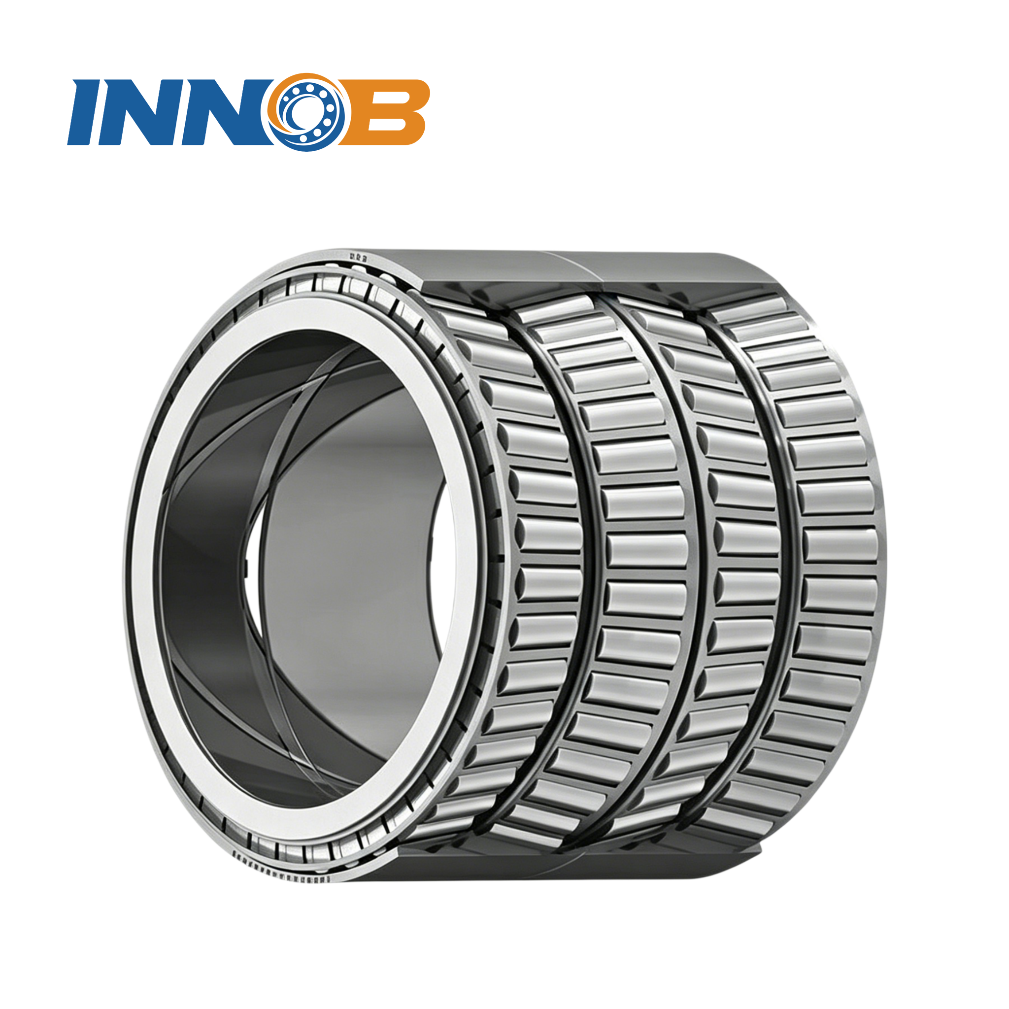
rolling-mill case where four-row tapered bearings are the norm, see
rolling mill bearing selection.
10. The checks that come after life
Passing the life calculation is necessary, not sufficient. Run these before issuing a purchase
spec:
| Check | What to verify | This example |
|---|---|---|
| Speed | n·dm against the catalogue limiting speed for the lubricant and cage | dm = (70+125)/2 = 97.5 mm; n·dm = 70,200 mm·rpm — comfortable for grease |
| Minimum load | Roller and thrust types need a minimum load to prevent roller/ball skidding | 8 kN radial is well above typical minimums for this size |
| Operating clearance | Interference fit + inner/outer ring temperature difference consume clearance; may push you from CN to C3/C4 | 75 °C with an interference inner-ring fit → check whether C3 is needed; see bearing clearance guidance |
| Lubrication | Grease vs oil, base-oil viscosity at operating temperature, relubrication interval, EP additives for shock loads | Grease, EP2-class, interval set by 75 °C and contamination; see lubricant selection notes |
| Sealing & contamination | Open, shielded (ZZ) or sealed (2RS); dust/water ingress | Welded-frame industrial environment → sealed or well-protected housing |
| Fits & mounting | Shaft/housing tolerances, shoulder squareness, mounting method (never hammer through rolling elements) | Verify ISO 286 fits and shoulder perpendicularity before assembly |
11. Five mistakes the arithmetic catches
- Selecting by bore diameter alone. Bore is set by the shaft; capacity, speed and
misalignment decide the type. A 6314 and a 22214 share a 70 mm bore and behave nothing alike. - Ignoring the axial component because it is “small”. At Fa/Fr = 0.313
it crossed the e threshold and changed both X and Y, raising
P by up to ~58% depending on type (10.40 kN for the tapered pair vs 16.39 kN for
the spherical roller). That is a life change of several multiples. - Assuming the highest C wins. Candidate C had the highest C and the
highest P; only the exponent made it competitive. - Sizing life before fixing alignment. Candidate B computed 257,000 h and was
still the wrong bearing for this frame. Hard constraints outrank life. - Treating a single bearing as the whole arrangement. Axial load in one
direction, thermal expansion, and shaft locating/floating duties often require a matched pair
or a dedicated thrust bearing. See angular contact vs deep
groove ball bearings and where thrust bearings are used.

12. Quick application → type map
| Application profile | First type to evaluate | Watch out for |
|---|---|---|
| High speed, moderate radial + some axial, clean | Deep groove ball | Check Fa/Fr against e; C3 if hot |
| Combined load, high stiffness, precise axial location | Paired angular contact or paired tapered roller | Preload/endplay setting; alignment |
| Heavy radial, shock, shaft deflection | Spherical roller | Speed limit, minimum load, cost |
| Very heavy radial, no axial, high speed, axial float needed | Cylindrical roller (NU/N) | Needs a separate axial locating bearing |
| Overwhelmingly axial, vertical shaft | Thrust ball / thrust roller / spherical roller thrust | No radial capacity; minimum load |
| Very limited radial space | Needle roller or thin-section | Shaft hardness, alignment sensitivity |
| Combined load + tilting moment, slow rotation | Four-point contact / crossed roller slewing | Bolt pattern, mounting-face flatness |
| Rolling mill / very heavy radial, moderate speed | Four-row tapered or four-row cylindrical | Lubrication, sealing, mounting sequence |
Browse our deep groove ball bearings,
tapered roller bearings,
spherical roller bearings,
cylindrical roller bearings,
thrust bearings,
thin-section bearings and
slewing bearings to see the ranges available for each family
in the matrix.

Send us the load case, get a sized comparison
The method above is exactly what our engineers run when a customer sends an application. Give us
Fr, Fa, speed and duty cycle, target life, misalignment, temperature, and your
envelope limit, and we will compute P and L10h for the viable types,
then quote the shortlist side by side — including what would have to change in the surrounding
structure. Contact our engineering team with your operating data.
Related reading
- Crossed Roller vs Ball Slewing Bearings: When to Choose — the same decision-matrix approach applied to slewing rings.
- The Types of Ball Bearings — a closer look at the ball-bearing families in the matrix.
- How to Choose the Right Slewing Bearing — building the load case for slow-rotating structures.
- Tapered Roller Bearing Selection Guide — paired arrangements, preload and endplay.
- Spherical & Cylindrical Roller Bearings — the two high-capacity roller families compared.
- The Importance of Bearing Clearance — why CN, C3 and C4 matter after mounting.
- Rolling Bearings vs Slewing Bearings — where the two product families diverge.
Frequently Asked Questions
What is the first thing to determine when choosing a bearing type?
The direction and ratio of the load. Compute Fa/Fr: pure radial points to cylindrical or needle rollers, combined load to deep groove, angular contact, tapered or spherical types, and predominantly axial load to thrust bearings. Then apply speed, misalignment, envelope and life as successive filters.
Are roller bearings always stronger than ball bearings?
No. Roller bearings carry more radial load for the same envelope because line contact spreads the load, but ball bearings run faster, cooler, quieter and cheaper. Strength is conditional on load direction, speed and alignment, so a spherical roller bearing is a poor substitute on a high-speed precision spindle.
What is equivalent dynamic load P and why does it matter?
P is the single radial load that would produce the same fatigue life as the actual combined radial and axial loading. It is computed as fd*(X*Fr + Y*Fa), where X and Y come from the bearing type and the Fa/Fr ratio relative to the limit e. Because life scales with (C/P)^p, a small error in P becomes a large error in predicted life.
Why do ball and roller bearings use different life exponents?
ISO 281 uses p = 3 for ball bearings (point contact) and p = 10/3 for roller bearings (line contact), reflecting how contact stress and fatigue life scale with load. The higher roller exponent means roller life is more sensitive to the C/P ratio.
What is the C3 clearance and when do I need it?
C3 denotes greater-than-normal internal radial clearance. Interference fits and a hotter inner ring consume clearance during operation, so C3 (or C4) is used for electric motors, hot applications, heavy interference fits and many roller bearings. Choosing the wrong class can cause thermal runaway and seizure even when the size is correct.
Can I replace a deep groove ball bearing with a spherical roller bearing of the same bore?
Sometimes, but not as a blind swap. The spherical roller bearing handles misalignment and much higher radial load, but it has a lower speed limit, higher friction, a different axial-load factor Y, and usually a different width. Re-run the P and L10h calculation and check the housing fits and speed before substituting.
How much misalignment can each bearing type tolerate?
As an order of magnitude: tapered roller and angular contact pairs only a few arcminutes (~0.05 deg or less), deep groove ball around 0.15 deg, four-point contact around 0.1 deg, self-aligning ball up to ~2 deg, and spherical roller up to ~1.5 deg. Confirm exact values in the manufacturer's catalogue.
What should I send a supplier to get a correct bearing recommendation?
Radial and axial loads (including shock), speed and duty cycle, target L10h life, expected misalignment, operating temperature and lubricant, sealing needs, and the bore/OD/width envelope. With those inputs an engineer can compute P, required C and the shortlist of viable types instead of guessing from a part number.

