
Locating and Non-Locating Bearings: A Thermal Growth Example
Locating and Non-Locating Bearings: A Thermal Growth Example
Every two-bearing shaft arrangement asks the same question before it asks anything else:
which bearing holds the shaft axially, and which one lets it move? The reason is heat. A steel
shaft running 65°C above ambient grows by about 0.23 mm over a 300 mm bearing span — and by
nearly 1.9 mm over a 4 m span. That growth has to go somewhere. If both bearings are clamped against
it, the expansion stops being motion and becomes force: a parasitic axial load that can be
fourteen times the design thrust and cut calculated life from tens of thousands of
hours to tens of hours.
Bearing suppliers explain the principle correctly: one locating (fixed) bearing, one non-locating
(floating) bearing, and the formula ΔL = α·L·ΔT. Almost all of them stop
there. This article takes the three steps they skip. We compute how much growth a real shaft makes
(including what an aluminium housing does differently), turn that into a required axial float
with installation allowance and safety factor, show the life cliff when the float provided is
even a few hundredths of a millimetre short, and then convert the answer into a bearing choice:
internal float with an NU cylindrical roller, an outer-ring
sliding fit with a deep groove ball bearing, or a preloaded
paired arrangement.
This is the third piece of a connected series. Our
bearing load calculation guide ended with a shaft whose floating seat A
carried only 4.58 kN radial and whose locating seat B carried all 2.500 kN of axial thrust. This
article explains why that split is deliberate and how much float seat A must provide to keep
it valid.
About the numbers: the expansion coefficients, stiffness, allowance,
safety factor, ratings and life figures below are illustrative magnitudes for teaching the
method, not catalogue values for any specific product. Substitute your actual geometry,
temperatures, fits and manufacturer ratings before designing an arrangement.
1. Why two locating bearings is the classic installation error
Take a shaft held axially at both ends and heat it. Steel wants to elongate; the two bearings
refuse to let it. The shaft cannot win, so it pushes on both bearings with a force set by the axial
stiffness of the shaft, the bearings and the housing. That force was never in the load calculation,
because it does not come from the machine’s duty — it comes from the installation itself.
The consequences are distinctive, which is why an experienced engineer recognises them quickly:
- Bearing temperature rises with no change in load. Extra axial force raises contact
load, which raises friction, which raises temperature — a feedback loop. - Life collapses. In the worked case below, a fully restrained 0.234 mm of growth
produces 35.1 kN of parasitic axial force and drops predicted life from 65,623 h to
roughly 42 h. - Failure looks like overload, not misinstallation. Raceways spall, preload climbs,
and the report blames the bearing or the lubricant.
The fix is a division of labour. The locating bearing is fixed to both shaft and
housing and carries radial load plus axial load in both directions. The non-locating
bearing carries radial load but is free to move axially, so it absorbs thermal growth without building
force. Between them the shaft is positioned in space yet free to breathe.
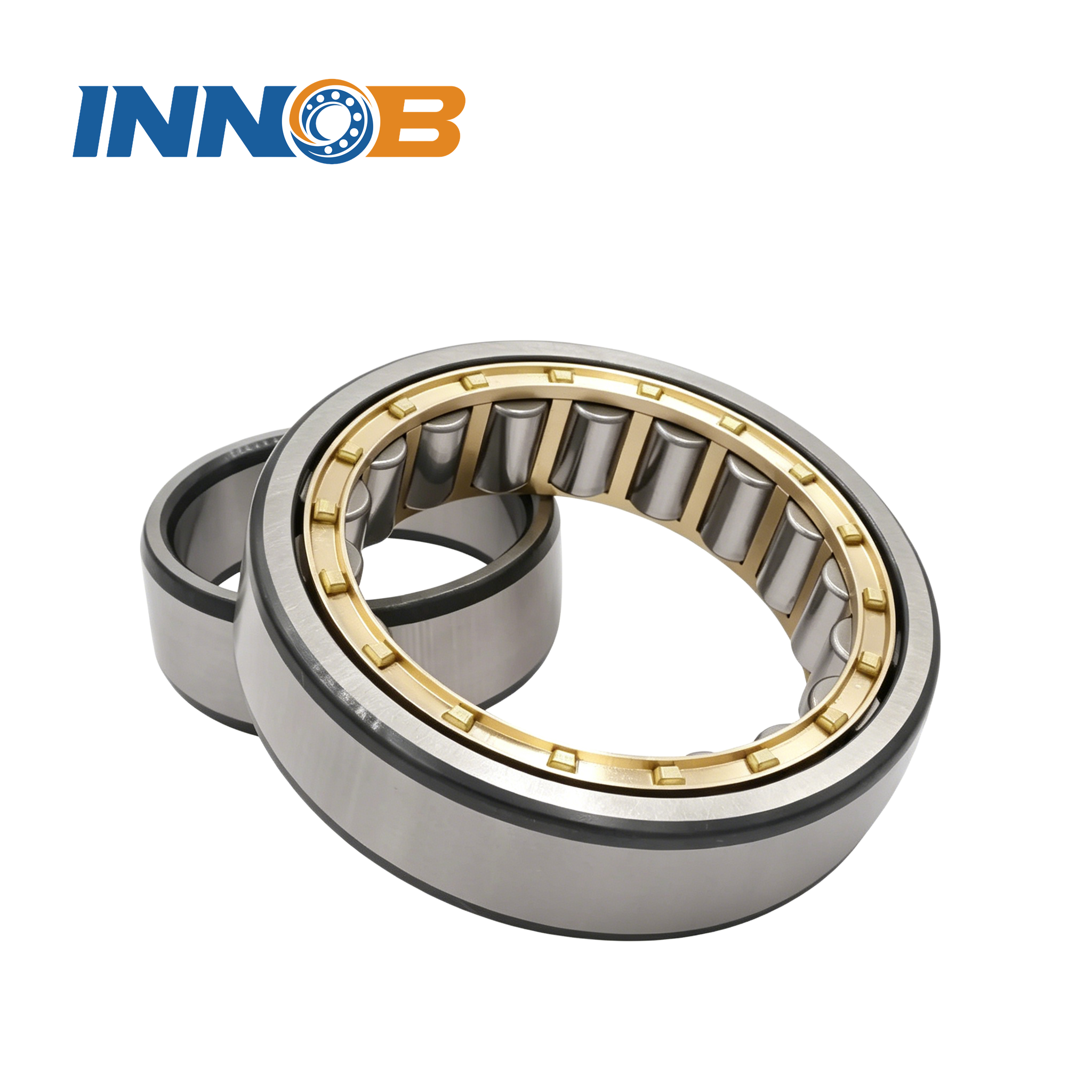
axially relative to the flangeless raceway, so both rings can be mounted with an interference fit
while the bearing still floats internally.
2. The decision chain at a glance
Five steps, each with one output. The competitive literature covers step 1 and jumps to a bearing
type. Steps 2 and 3 are where an arrangement succeeds or fails, and they are what this article adds.
| Step | What you compute | Output | Common trap |
|---|---|---|---|
| 1 | Thermal growth of shaft relative to housing | ΔL in mm | Using ambient temperature instead of the running shaft temperature |
| 2 | Required float = growth + allowance, with safety factor | sreq in mm | Matching float to ΔL with zero installation margin |
| 3 | Life penalty if available float falls short | parasitic F, L10h | Assuming “a bit less float” is a small error |
| 4 | Float mechanism: internal, sliding fit, or paired arrangement | Bearing family | Choosing an NUP when a floating bearing is needed |
| 5 | Which end locates, and the fits on each ring | Arrangement drawing | Letting the housing dictate the locating end arbitrarily |
3. Step 1 — how much does the shaft actually grow?
The basic relation is ΔL = α·L·ΔT, where α is the linear
expansion coefficient (about 12 × 10−6 /°C for steel), L is the distance
between the locating bearing and the floating bearing, and ΔT is the shaft’s temperature rise
from assembly to running condition.
Keep the model conservative: assume the housing stays near ambient while the shaft reaches its
running temperature. That makes the whole shaft expansion the floating seat’s problem, which is the
safe way to design.
ΔL = α · L · ΔT
Case A is the 300 mm-span gear drive from our load-calculation article: the shaft
runs 65°C above ambient (20°C → 85°C). Case B is a long dryer or
conveyor drum shaft, 2,400 mm between bearings, 45°C rise.
| Case | Span L | ΔT | ΔL = αLΔT |
|---|---|---|---|
| A — compact gear drive | 300 mm | 65°C | 12e−6 × 300 × 65 = 0.234 mm |
| B — long drum shaft | 2,400 mm | 45°C | 12e−6 × 2,400 × 45 = 1.296 mm |
A single number is misleading because growth scales with both length and temperature. This grid
shows the same steel shaft at several spans and rises; it is the quickest way to see whether thermal
growth is a rounding detail or a design driver.
| Span L | ΔT = 30°C | ΔT = 45°C | ΔT = 65°C |
|---|---|---|---|
| 300 mm | 0.108 mm | 0.162 mm | 0.234 mm |
| 600 mm | 0.216 mm | 0.324 mm | 0.468 mm |
| 1,000 mm | 0.360 mm | 0.540 mm | 0.780 mm |
| 1,500 mm | 0.540 mm | 0.810 mm | 1.170 mm |
| 2,400 mm | 0.864 mm | 1.296 mm | 1.872 mm |
| 4,000 mm | 1.440 mm | 2.160 mm | 3.120 mm |
Below roughly 0.2 mm, a standard bearing’s internal clearance can quietly absorb the growth and
the arrangement is forgiving. Above about 1 mm, growth becomes the dominant axial design constraint
and the float mechanism must be chosen deliberately. A 4 m shaft at 65°C needs more than 3 mm of
travel — far beyond what a deep groove ball bearing sliding in its housing can reliably give.
4. Step 2 — from growth to required axial float
The float you must design in is not equal to ΔL. Two more quantities belong in the sum: an
installation allowance for tolerance stack-up (shoulder positions, housing bore
depth, thermal growth during assembly, measurement error) and a safety factor for
uncertainty in the running temperature.
sreq = fs · (ΔL + allowance)
Using an illustrative allowance of 0.10 mm and a safety factor fs = 1.30:
| Case | ΔL | Allowance | fs | Required float sreq |
|---|---|---|---|---|
| A — 300 mm gear drive | 0.234 mm | 0.10 mm | 1.30 | 0.434 mm |
| B — 2,400 mm drum | 1.296 mm | 0.10 mm | 1.30 | 1.815 mm |
Note that safety is applied to the whole bracket, including the allowance — growth you did
not budget for is the one that hurts. Notice also how the allowance, fixed at 0.10 mm, matters
greatly for the short shaft (it is nearly a third of the growth) and negligibly for the long one.
Short shafts are dominated by installation tolerance; long shafts by expansion itself.
The number on the drawing should be a minimum travel with the shaft at its cold position,
plus a clear statement of which direction the shaft grows and where the locating datum is. “Allow
for thermal expansion” is not a manufacturable instruction; “floating bearing to provide at least
0.45 mm axial travel from the cold position toward the gear” is.
5. Step 3 — the life cliff when float runs short
This is the calculation almost nobody publishes, and it is the reason a float specification
deserves the same attention as a load rating. Treat the shaft and bearing stack as a spring with an
axial stiffness k — an illustrative 150 kN/mm here. If the bearing provides float s but
the shaft grew by ΔL, the shortfall δ = ΔL − s is converted into parasitic
axial force:
Fparasitic = k · (ΔL − s)
Add that force to the locating bearing’s axial load and recompute the equivalent dynamic load,
using the same illustrative factors as the load-calculation article
(fd = 1.3, X = 0.67, Y = 2.9, Fr = 8.0 kN, design Fa = 2.5 kN,
C = 178 kN, p = 10/3, 23.15 h per million revolutions). Case A needs 0.234 mm of float:
| Float provided s | Shortfall δ | Parasitic F | Fa total | P | L10h | vs design |
|---|---|---|---|---|---|---|
| 0 mm (both ends fixed) | 0.234 mm | 35.1 kN | 37.6 kN | 148.7 kN | 42 h | 0.1% |
| 0.100 mm | 0.134 mm | 20.1 kN | 22.6 kN | 92.2 kN | 208 h | 0.3% |
| 0.150 mm | 0.084 mm | 12.6 kN | 15.1 kN | 63.9 kN | 704 h | 1.1% |
| 0.200 mm | 0.034 mm | 5.1 kN | 7.6 kN | 35.6 kN | 4,939 h | 7.5% |
| 0.234 mm (exact) | 0 | 0 | 2.5 kN | 16.39 kN | 65,623 h | 100% |
| 0.434 mm (= sreq) | 0 | 0 | 2.5 kN | 16.39 kN | 65,623 h | 100% |
Read the last two rows carefully. Providing exactly the growth (0.234 mm) already recovers
full design life; the extra allowance is insurance against uncertainty, not extra capacity. But
missing it by only 0.034 mm — 0.200 mm provided against 0.234 mm needed, a 15%
shortfall — still costs 92% of calculated life. There is no gradual degradation
here. Because life scales with (C/P)10/3 and P has a large axial term, float shortfall is
amplified into a cliff.
For Case B the arithmetic is brutal: a fully restrained 1.296 mm of growth at the same stiffness
would generate 194.4 kN of parasitic force, well beyond what a bearing of this class can carry. Long
shafts are not a borderline case — they must have a positive, verified float mechanism.
The model assumes the entire shortfall loads the locating bearing and uses an
illustrative axial stiffness. Real stiffness depends on the bearing, fits and housing; the point of
the table is the shape of the curve — a steep, nonlinear penalty — not the exact
hour figures.
6. Step 4 — three ways to make a bearing float
Once the required float is known, choose a mechanism. There are three, and they are not
interchangeable.
| Mechanism | How it floats | Typical travel* | Ring fits | Best for |
|---|---|---|---|---|
| Internal float — NU / N cylindrical roller | Rollers move axially on the flangeless raceway | ~1.5–3.0 mm | Both rings can be interference fits | High radial load, high speed, no axial constraint |
| Outer-ring sliding fit — deep groove / spherical roller | Outer ring slides in the housing bore | ~±1–2 mm, seat limited | Inner ring interference, outer ring clearance (H6/G6) | Moderate duty, simple housing, short travel |
| Adjusted / paired arrangement — opposed angular contact or tapered pair | Set clearance or light preload between the two bearings | Set at assembly, not free float | Both rings located; adjust with shims / nut | Rigid, precise shafts; short spans; gear positioning |
*Illustrative travel ranges. Always take the actual permissible
axial displacement from the manufacturer’s catalogue for the specific bearing and fits.
Internal float is the cleanest solution because the movement happens inside the bearing: both rings
can be clamped, so there is no fretting between an outer ring and a housing bore. Its limit is that
it gives no axial location at all — a pure NU or N bearing cannot locate the shaft in either
direction, so the other end must do it.
An outer-ring sliding fit is cheap and works for short travel, but the sliding happens under the
bearing’s full radial load. On a heavily loaded spherical roller that sliding force can be large
enough to resist movement or fret the housing bore; it is a common source of “the bearing was fine
but the housing wore out”. See our note on
bearing clearance for how the operating fit changes once the machine
is hot.
An adjusted pair does not float freely at all: it sets a defined clearance or light preload. It is
excellent for rigidity and axial positioning on short shafts, but it is the wrong answer when the
required growth from step 2 is large — a preloaded pair cannot absorb 1.8 mm of expansion.
7. Internal float: the NU cylindrical roller solution
An NU cylindrical roller bearing has two ribs on the inner ring
and none on the outer ring (an N bearing reverses this). The rollers can travel axially along the
flangeless raceway, so the bearing accommodates shaft growth internally. Because no external sliding
is needed, the inner ring can be an interference fit on the shaft and the outer ring an interference
fit in the housing — eliminating ring creep at both seats.
| Design point | Recommendation | Why |
|---|---|---|
| Internal axial travel | ≥ sreq plus margin | Check catalogue permissible displacement for the chosen size and fits |
| Inner ring fit | Interference (e.g. k6/m6 family) | Prevent the ring creeping on a rotating shaft under radial load |
| Outer ring fit | Interference or transition | No sliding needed; avoid housing-bore fretting |
| Minimum radial load | Verify | Rollers can skid if radial load is too low for the speed |
| Location duty | None — pair with a locating bearing | NU/N carry no axial load and cannot position the shaft |
For Case A (sreq = 0.434 mm) a standard NU of the right series has ample internal travel.
For Case B (1.815 mm) the travel must be checked explicitly: some sizes offer enough, others do not,
and a design that assumes “cylindrical rollers float” without verifying the number has repeated the
original mistake at a worse scale.
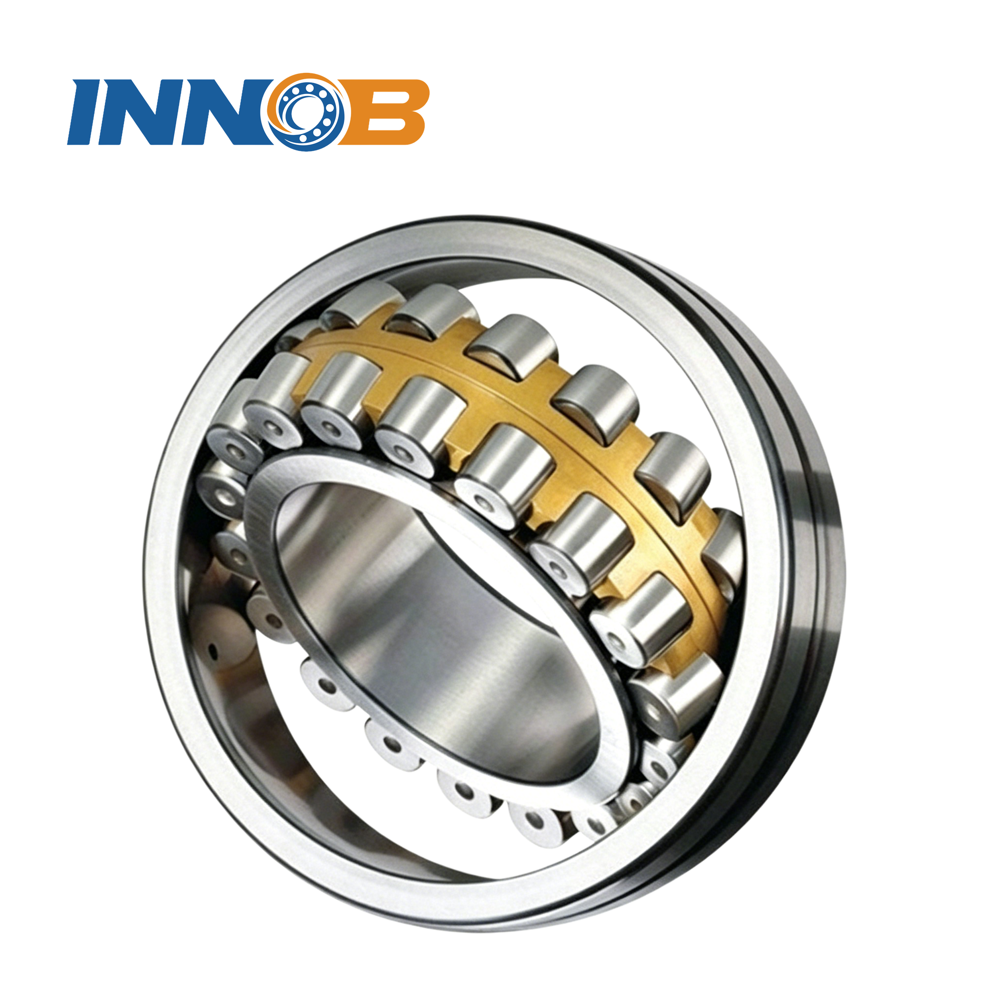
thrust in both directions. It belongs opposite the floating NU, not in the floating seat under
heavy radial load where outer-ring sliding would be required.
8. Outer-ring sliding fit: deep groove and spherical roller options
If radial load is modest and travel is short, a
deep groove ball bearing can float by sliding its outer ring in the
housing bore with a clearance fit (a G6/H6-type housing fit in illustrative terms), while the inner
ring stays clamped to the shaft. A
spherical roller bearing can be used the same way when
misalignment demands self-aligning capability.
The sliding fit trades simplicity for three risks:
- Travel is seat-limited. The outer ring can only slide as far as the housing
shoulders allow, typically ±1–2 mm in ordinary arrangements — not enough for
Case B. - Sliding happens under load. With the full radial reaction pressing the outer
ring into the bore, the friction that resists movement is not small. Thermal growth can be
partly absorbed by elastic deflection instead of sliding, recreating the parasitic-force problem. - Fretting corrosion. Machine vibration rocks a loosely fitted outer ring in its
bore, producing the rust-coloured smear and black powder that
failure analysts recognise as fretting.
If this mechanism is chosen, specify the housing fit explicitly, keep the bore surface finish and
roundness tight, and confirm that the available travel exceeds sreq with the ring at its
cold-position limit. A deep groove ball bearing used this way still needs a separate locating bearing
at the other end; it cannot take thrust and float at the same time. Our
angular contact vs deep groove comparison explains why the deep
groove bearing’s axial capacity is limited when a genuine locating function is needed.

but its travel is limited by the housing shoulders and it transfers no axial load.
9. The third option: an adjusted pair
For short, stiff shafts where axial positioning matters — machine spindles, precise gear
mounting, wheel hubs — the answer is often not “one fixed, one floating” but two bearings
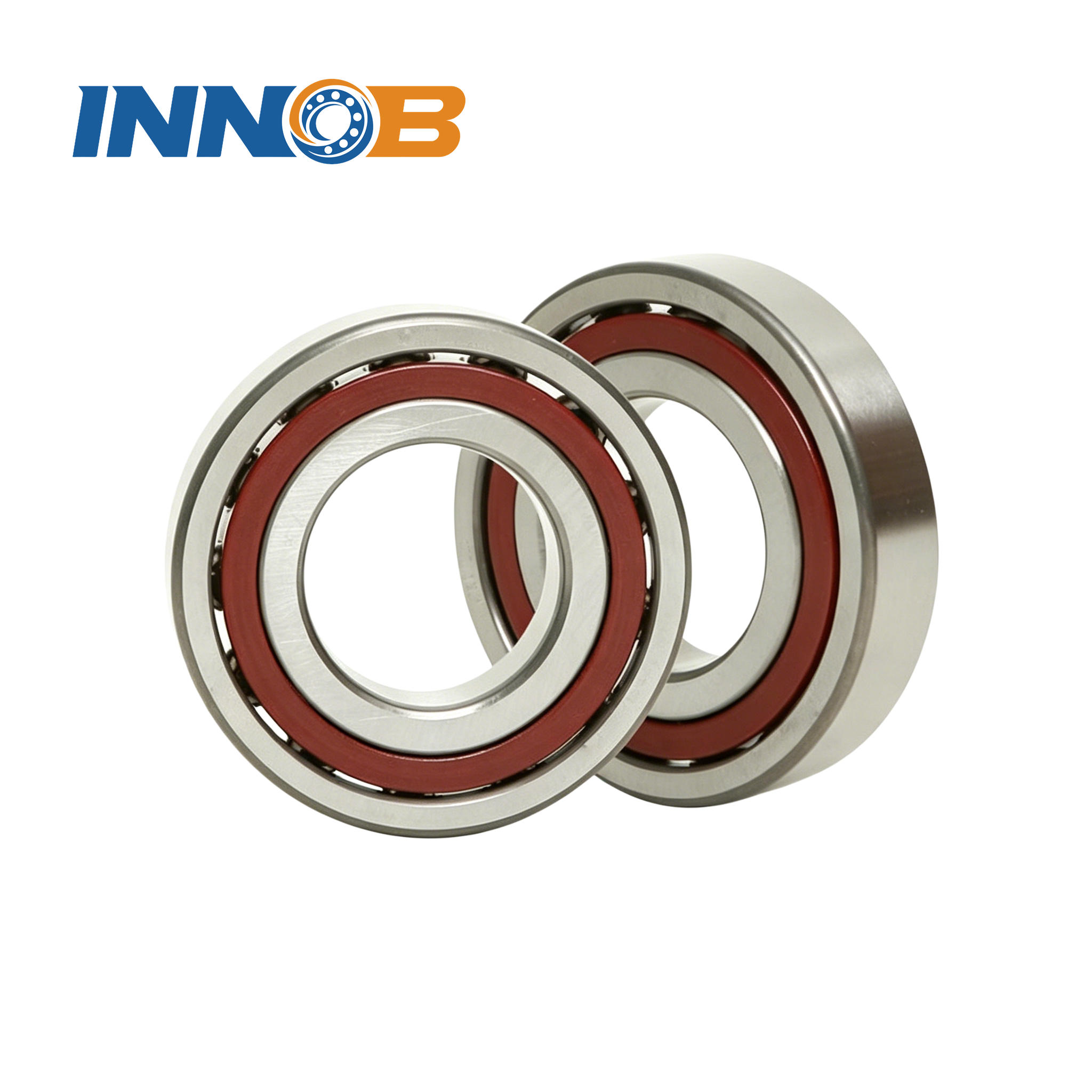
mounted against each other. Opposed
angular contact ball bearings or
tapered roller bearings are set with a defined clearance or light
preload, giving high rigidity and accurate axial location.
The trade-off is that an adjusted pair consumes the thermal-growth budget at assembly. It has no
free float; any expansion shows up as a change in preload. That is acceptable when the span is short
and the temperature rise modest, and dangerous when step 2 returned more than about a millimetre.
For a long, hot shaft the usual pattern is a locating adjusted pair at one end and an NU floating
bearing at the other — rigidity where it matters, float where it is needed. Our
tapered roller bearing selection guide covers preload and endplay setting
for the locating pair.
A thrust bearing is not a solution to floating. It carries axial
load in one direction only, cannot locate both ways on its own, and must be paired with a radial
bearing; dropping one into a shaft that also carries 8 kN radial accomplishes none of the float
requirements calculated above.
but they are set at assembly and cannot absorb large thermal growth on a long shaft.
10. Step 5 — which end should locate?
Once the float mechanism is settled, decide which seat is fixed. Three rules, in priority order:
- Where the axial load already is. In the gear drive from article #3, the helical
gear generates 2.500 kN of thrust. Letting the bearing nearest the gear locate keeps that force
on the shortest, stiffest load path; that is why seat B was chosen as the locating bearing and
seat A as floating. - Short distance to the heat source and the locating datum. Put the locating
bearing where the shaft’s axial position is measured from, so growth proceeds away from a known
reference toward the floating end. - Access for adjustment. The locating end often needs shims or a locknut to set
preload or endplay; put it where a fitter can reach it.
Write the decision on the drawing: which bearing locates, the cold-position datum, the direction of
growth, and the minimum travel the floating end must provide. Ambiguity here is what produces the
“both ends clamped” installation in the first place.
A special case is the slow-rotating structure — a crane turntable or excavator ring —
where the “shaft” is a ring bolted to a frame and the load case is axial force plus tilting moment,
not gear thrust. The locating/floating logic still applies to how the ring is supported, but the
numbers come from a different model; see our
slewing bearing selection overview and the
crossed roller vs ball comparison.
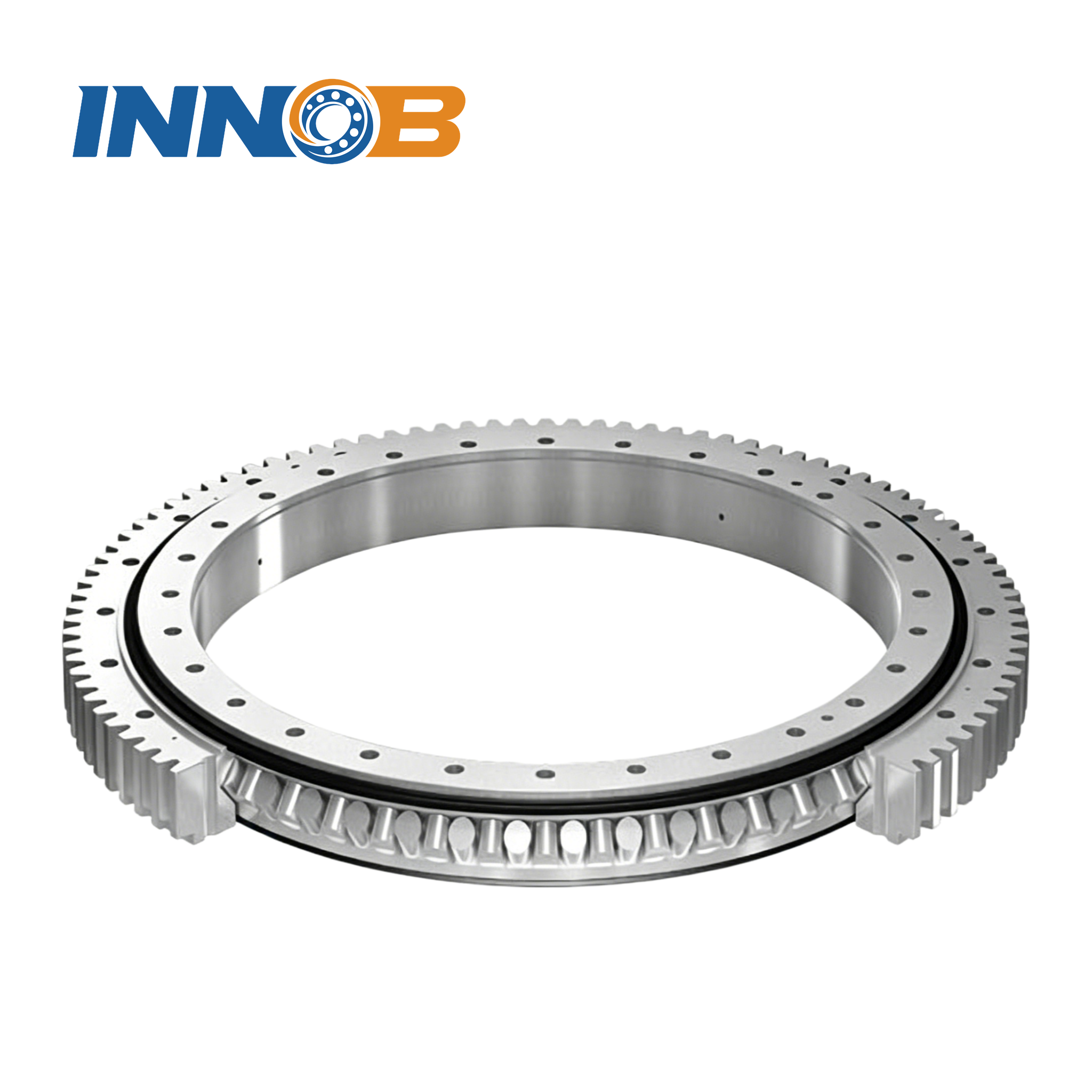
moment at the bolt circle rather than from shaft reactions.
11. Housing material and differential expansion
So far the housing has been treated as static. In reality it expands too, and what matters is the
difference between shaft and housing. Using the same 300 mm span and 65°C rise, with
illustrative housing coefficients:
| Housing material | α housing | Relative growth vs steel shaft* |
|---|---|---|
| Cast iron | ~10.5 × 10⁻⁶ | 0.029 mm |
| Steel | ~12 × 10−6 | 0 mm (matched) |
| Aluminium | ~23 × 10−6 | 0.215 mm |
*If both reach the same temperature. The sign reverses if the
housing runs hotter than the shaft; use the actual running temperatures in both parts.
An aluminium housing expands almost twice as much as the steel shaft over the same temperature
rise. If the shaft is hotter — the usual case in a gearbox — the two partially cancel and
the required float is smaller than the conservative estimate. If the housing is the hotter part (an
externally heated drum, a sun-lit outdoor pedestal), the relative movement reverses and the float must
be provided in the opposite direction. Either way the aluminium case is nearly as large as the entire
steel-shaft growth in Case A, so it cannot be ignored.
This is why an arrangement copied from a cast-iron housing into an aluminium one can fail: the
geometry and the bearings are identical, but the differential expansion budget changed by an order of
magnitude. Check the housing coefficient and its running temperature before signing off any float
figure.
12. Worked decision: the gear-drive shaft from article #3
Put the whole chain together on the shaft we already sized. Step 1 gave the loads: floating seat A
at 4.58 kN radial, locating seat B at 8.04 kN radial plus 2.500 kN axial. Add the thermal model from
this article with an illustrative 300 mm span, 65°C shaft rise, steel housing:
| Question | Result | Decision |
|---|---|---|
| How much does the shaft grow? | ΔL = 0.234 mm | Float is mandatory, not optional |
| Required float? | sreq = 0.434 mm | Specify ≥ 0.45 mm at cold position |
| Cost of a 0.034 mm shortfall? | Life 4,939 h vs 65,623 h | Design margin is cheap; do not skip it |
| Float mechanism? | Internal float ~1.5–3 mm available | NU cylindrical roller at seat A |
| Locating bearing? | Carries Fr 8.04 kN + Fa 2.500 kN | Spherical roller at seat B (per selection guide) |
| Ring fits? | A: both rings clamped; B: inner clamped, outer located | No sliding at either seat |
The result is a coherent arrangement: an NU floating bearing that needs no housing sliding, a
locating spherical roller that takes the gear thrust on the shortest load path, and a drawing that
states the cold-position float explicitly. It is the same pair of seats the
load-calculation article arrived at — now with the thermal reason and
the float number behind it.
For the heavy-duty end of the range, the same reasoning applies with larger forces and longer
spans; our rolling mill bearing notes and
spherical & cylindrical roller guide cover that class.
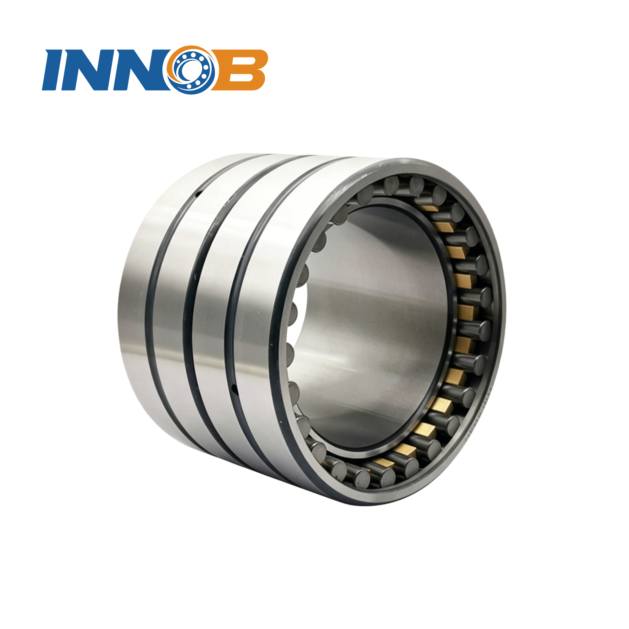
is a first-order constraint on the arrangement rather than a detail.
13. Eight mistakes that turn growth into a bearing failure
| Mistake | What happens | Fix |
|---|---|---|
| Clamp both bearings axially | Growth becomes parasitic force; life collapses | One locating, one floating seat |
| Size float to ΔL with no allowance | Tolerance stack-up consumes the margin | Add installation allowance and safety factor |
| Use an NUP as the floating bearing | NUP locates both ways and cannot float; it restrains growth | Use NU or N for internal float |
| Specify “allow for expansion” on the drawing | Not manufacturable or verifiable | State minimum travel, datum and growth direction |
| Use a sliding outer-ring fit under heavy radial load | High sliding force, fretting, housing-bore wear | Use internal float with both rings clamped |
| Ignore housing material | Aluminium moves ~0.215 mm differently in Case A | Include housing coefficient and temperature |
| Assume the housing stays cold without checking | Differential expansion sign can reverse | Measure or estimate both running temperatures |
| Reuse a preloaded pair on a long, hot shaft | Preload climbs with growth; no float budget | Locating pair at one end, NU float at the other |
Every one of these is an installation or specification decision, not a bearing-quality problem.
That is the point: the bearing is usually the last thing to blame and the first thing to replace.
14. What to put on the drawing and what to measure
A float arrangement is only as good as the information given to the person assembling it. This is
the minimum set we ask for when reviewing a drawing:
| Item | Why it is needed | How it is obtained |
|---|---|---|
| Shaft and housing running temperatures | Set ΔT for both parts | Measurement on a running machine, or duty estimate |
| Distance from locating bearing to floating bearing | The length L in αLΔT | Assembly drawing |
| Minimum axial travel at the floating seat | The manufacturable expression of sreq | Step 2 calculation |
| Which bearing locates; cold-position datum | Defines the direction of growth | Arrangement decision, step 5 |
| Fit class for each ring at both seats | Prevents creep and unintended sliding | Load and float mechanism |
| Permissible axial displacement of the chosen bearing | Confirms the mechanism can deliver sreq | Manufacturer catalogue |
| Endplay or preload setting method | Reproducible assembly for a locating pair | Shim stack, locknut torque, or gauge |
On the machine, the useful checks are simple: measure the housing temperature at the bearing seats
after a heat soak, confirm the shaft can be pushed axially by at least the specified amount with the
machine cold and stopped, and record the axial position of the shaft relative to the housing at
assembly. A bearing that runs hot shortly after a rebuild is often telling you that this float was
never actually present.
Send us the arrangement, get the float checked
The chain above is what our engineers run before recommending a locating/floating arrangement:
span, running temperatures, shaft and housing materials, the loads at each seat, and the fits you plan
to use. Send us those inputs and we will return the required axial float, the parasitic-force and life
impact if it is short, and the bearing families that can deliver the travel — including what has
to change in the housing if none of them can.
Send your arrangement data to our engineering team.
You can also browse our cylindrical roller,
deep groove ball,
spherical roller,
tapered roller and
angular contact bearing families for the types that appear in this
decision.
Related reading
- Bearing Load Calculation: From Shaft Forces to Fr, Fa and L10 —
the shaft whose axial split (A floating, B locating) this article explains. - Bearing Type Selection: A Decision Matrix with a Worked Example —
how the load case becomes a bearing choice. - The Importance of Bearing Clearance — what fits and
temperature do to the clearance you selected. - Spherical & Cylindrical Roller Bearings — the locating and
floating roller families used in the worked arrangement. - Tapered Roller Bearing Selection Guide — preload and endplay
for an adjusted locating pair. - Angular Contact vs Deep Groove Ball Bearings — axial
capacity and X/Y factors when choosing the locating bearing. - The Types of Ball Bearings — ball families including the
sliding-fit floating option. - How to Choose the Right Slewing Bearing — the alternative
load model for slow-rotating structures.

it with a floating NU at the other end when the span is long.
Frequently Asked Questions
What is the difference between a locating and a non-locating bearing?
The locating (fixed) bearing holds the shaft axially in both directions and carries radial plus axial load. The non-locating (floating) bearing carries radial load but is free to move axially, so it absorbs thermal growth without building force. A typical arrangement uses one of each.
How much does a bearing shaft expand with temperature?
Use dL = alpha * L * dT. For steel, alpha is about 12e-6 per degC. A 300 mm shaft rising 65 degC grows 0.234 mm; a 2,400 mm shaft rising 45 degC grows 1.296 mm. Growth scales with both span and temperature rise, so long hot shafts need a deliberately sized float.
Which bearing type is used as a floating bearing?
An NU or N cylindrical roller bearing floats internally because the rollers can move axially along a flangeless raceway, allowing both rings to be interference-fitted. A deep groove ball bearing with a sliding outer-ring fit is a cheaper option for short travel. An NUP bearing does NOT float – it locates in both directions.
What happens if thermal expansion is restrained?
The growth turns into parasitic axial force F = k * shortfall. In the worked case a fully restrained 0.234 mm produces 35.1 kN – about 14 times the 2.5 kN design thrust – and cuts calculated L10 life from 65,623 h to about 42 h.
How much axial float should I design in?
Required float = safety factor * (thermal growth + installation allowance). With an illustrative 0.10 mm allowance and 1.30 safety factor, 0.234 mm of growth needs 0.434 mm of travel. Specify it as a minimum from the cold position, plus the growth direction, on the drawing.
Can a deep groove ball bearing be used as a floating bearing?
Yes, with a clearance fit between its outer ring and the housing bore. Its travel is limited (roughly +/-1-2 mm in ordinary seats), and sliding under heavy radial load can cause fretting and housing wear. Internal-float cylindrical roller bearings are preferred for heavy duty or long travel.
Does the housing material matter for thermal growth?
Yes. What counts is shaft-versus-housing differential expansion. Over a 300 mm span at 65 degC, an aluminium housing moves about 0.215 mm differently from a steel shaft, while cast iron is only about 0.029 mm. Check both materials' coefficients and running temperatures.
Can a preloaded bearing pair accommodate thermal growth?
Only a little. An opposed angular-contact or tapered pair is set at assembly and has no free float; expansion raises preload. For a long hot shaft, use a locating pair at one end and a floating NU cylindrical roller bearing at the other.